Isostack Tool Help – Right Panel
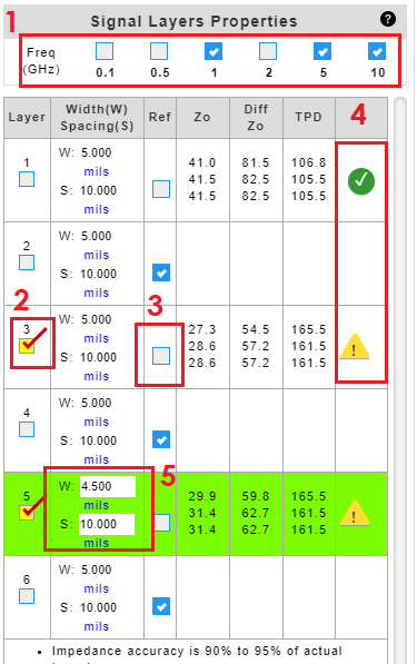
  1. Check to select frequencies to calculate impedance.
  2. Check to highlight the copper layer of interest.
  3. Uncheck reference check box to designate a signal layer. By default, all layers are treated as a reference plane.
  4. 4. A ‘green’ Okcheck mark indicates that the input criteria meet the constraints for the equations used in IsoStack. A ‘yellow’ Warning warning sign indicates that the input criteria do not meet the constraints for the equations used in IsoStack. Click on the icon to reveal the parameters and criteria.
  5. Click to enter or edit trace properties.
NOTE:
Formulas from IPC-2141A Design Guide for High-Speed Controlled Impedance Circuit Board.

16 July 2021

Related Posts

UAV FW Blog
PCBs Lighten the Loads for Commercial UAVs
Drones or unmanned aerial vehicles (UAVs) are typically associated with military users, although a growing number of applications are being found for UAVs in commercial, industrial, and even medical markets. Commercial users await approval from key government agencies, such as the U. S. Federal Aviation Administration, for properly authorized use…
Isola Names New CFO
CHANDLER, Ariz., August 15, 2016 — Isola, a market leader in copper-clad laminates and dielectric prepreg materials used to fabricate advanced multilayer Printed Circuit Boards (PCBs), announced that it has appointed Ken Rizvi as Chief Financial Officer, effective immediately. Rizvi succeeds Interim CFO Donald Colvin, who will continue to serve…
Tpca Show Logo 6509
ISOLA TO EXHIBIT AT TPCA SHOW, OCTOBER 23-25, 2019